As mentioned many times, the projection center PC is an extremely important quantity and significantly determines in the end how (relatively) correct a crystal lattice can be characterized. It determines both the lattice parameter ratios and the angles between the basis vectors.
The preferred way in CALM is if PC would be known.
However, this is the exception rather than the rule, so an additional Kikuchi pattern from a known, ideally cubic phase as reference, taken in the immediate neighborhood and under practically identical conditions (same beam position), is the best prerequisite for correct results.
Please note: Since very often Kikuchi patterns are available, but neither the recording conditions nor even a reference pattern from another phase exist, CALM has a built-in emergency system that can determine PC.
This is also used to adapt known PC’s, because often their quality is far from the actual requirements of PC.
The four direction appraoch
As the name already says, the procedure uses 4 [uvw] and the lattice parameters defined in the gpd file to fit PC until all angles between these four directions matches best. Because of experimental reasons (imperfect trace selection) even for cubic phases this will never match perfectly.
The trick is to be able to index manually a few zone axis, i.e. to recognize mainly some of the symmetry axis in a cubic pattern. These are, as everybody knows, the four-fold axes along <001>, the three-fold axes along <111> and the 2-fold axes along <011>.
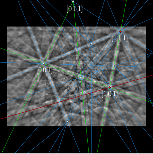
Possible indexing of four zone axes: [001], [101], [111] and [011]. The selction and description has to happen clockwise or anti-clockwise and exactly in this order. With which [uvw] you start is irrelevant. The used intersection points should simply form a convex quadrilateral.
The here used “Zoom in/out” is possible with the mouse wheel during pression Ctrl+Shift. The mouse pointer has to be on the gnomonic projection. The same works with the “Reciprocal lattice” display.
Procedure
- select radio button “All with” in “Poles”
- select radio button “Zone” in “Band edges”
- Press on “Calib.” in the PC menue at the bottom menu left.
This results in a message box asking for a solution, but it also opens the “PC determination” window displaying the lattice parameters defined in the gpd file. Default values are 1,1,1,90°,90°,90°. This is sufficient for a cubic phase. - Now select the red colored pole by Ctrl+LMB and enter in the input field above “Calib” the indices seperated by blanks, i.e. in this specific case: 1 [blank] 0 {blank] 1, which looks in real : 1 0 1.
- Confirm each input zone axis by pressing “Calib“.
This generates a new line in the opened “PC determination” window dscribing the number of points, the read indexing, and the [x,y] coordinates. - Now repeat 4. and 5. for the remaining points.
If something went wrong, you need to restart again by pressing “Reset” below the “Adopt” button. This deletes everything in the window. - After input of the last zone axis PC is immediately shown.
- Press “Adopt” to use this description as new PC.
Zone axis indexing
This procedure might look difficult on the first point of view, but often you have for the reference pattern an indexing of zone axes from your commercial EBSD system like below. There any combination of four poles can be used as long as their Intersections form a quadrilateral.
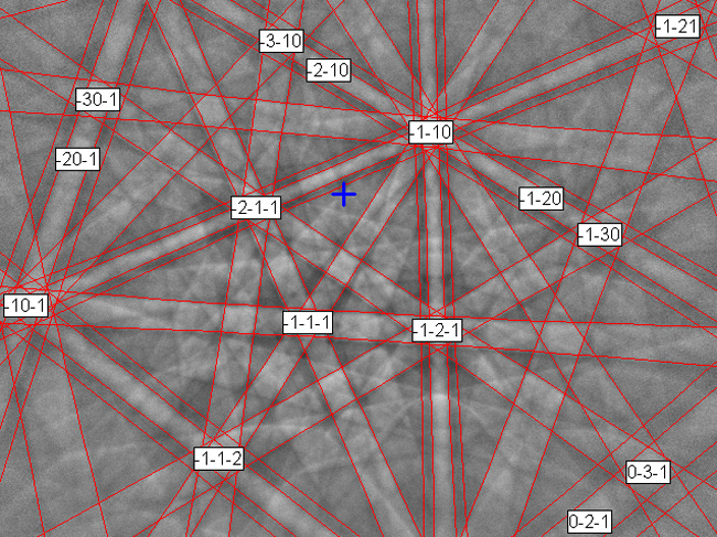
Indexed reference pattern with proposed pattern center. The pattern is quite correct but PCz is missing which results from the PC determination in CALM as PCz=0.659.